Matlab Exercise

MATLAB/Simulinkによる現代制御入門


Chapter 5: サーボシステムの設計


5.1 フィードフォワードを利用した目標値追従制御

5.1.1 定値の目標値への追従制御

Figure 5.1 track control using feedforwad

K: u(t)=kx(t)+hyref(t)                                                   (5.1)

0=Ax+buycref=cxAbc0xu=01ycref                                   (5.2)

x~(t):=x(t)-x,u~(t):=u(t)-u

稳态条件:

x˙=0,u˙=0, y=ycref

x~˙(t)=x˙(t)=Ax(t)+bu(t)=A(x~(t)+x)+b(u~(t)+u)=Ax~(t)+bu~(t)+Ax+bu=Ax~(t)+bu~(t)                           (5.3)

e(t)=ycref-cx(t)=ycref-c(x~(t)+x)   =-cx~(t)+ycref-cx=-cx~(t)                                          (5.4)

t 时,由 式(5.1) 得,

u=kx+hycref                                                                       (5.5)

式(5.1) 减去 式(5.5) 得, K:u~(t)=kx~(t)
如果按此种方法设计, t 时,有

x~(t)=eAc1x~(0)0                                                                       (5.6)

其中, Ac1:=A+bk ,即

e(t)=ycref-y(t)=-cx~(t)0  (y(t)yref(t)=ycref)                                (5.7)

K:u(t)=k(x(t)-x)+u=kx(t)+-k1xu=kx(t)+hycrefAbc0xu=01ycref                     (5.8)


Theorem 5.1:

h=-k1Abc0-101                                                                        (5.9)


Extra: Iterative control

discrete condition

x(t+1)=Ax(t)+Bu(t)y(t)=Cx(t)                                                                      (5.10)

ILC

x(t+1,k)=Ax(t,k)+Bu(t,k)y(t,k)=Cx(t,k)                                                                      (5.11)

objective and final state condition

limky(t,k):=y(t,)=ycref                                                (5.12)

error

e(t,k)=ycref-y(t,k), e(t,)=ycref-y(t,)=0                                             (5.13)

differential

Δu(t,k)=u(t,k+1)-u(t,k)Δx(t,k)=x(t,k+1)-x(t,k)Δy(t,k)=y(t,k+1)-y(t,k)                                          (5.14)

Δx(t+1,k)=x(t+1,k+1)-x(t+1,k)                   =Ax(t,k+1)+Bu(t,k+1)-Ax(t,k)-Bu(t,k)                    =AΔx(t,k)+BΔu(t,k)                                                                 (5.15)

Δe(t,k)=e(t,k+1)-e(t,k)                                              =-y(t,k+1)+y(t,k)                             =-Cx(t,k+1)+Cx(t,k)=-CΔx(t,k)=-CAΔx(t-1,k)-CBΔu(t-1,k)                 (5.16)

Δe(t+1,)=0Δx(t+1,)=AΔx(t,) + BΔu(t,) =0              (5.17)

control rule

u(t,k+1)=u(t,k)+Δu(t,k), Δu(t,k)=Ke(t,k)                       (5.18)

Δx(t+1,k)=AΔx(t,k)+BKΔe(t,k) e(t,k+1)=-CΔx(t,k)+e(t,k)                                                   (5.19)


5.2 サーボシステムと積分型コントローラ

5.2.1 サーボシステムと内部モデル原理
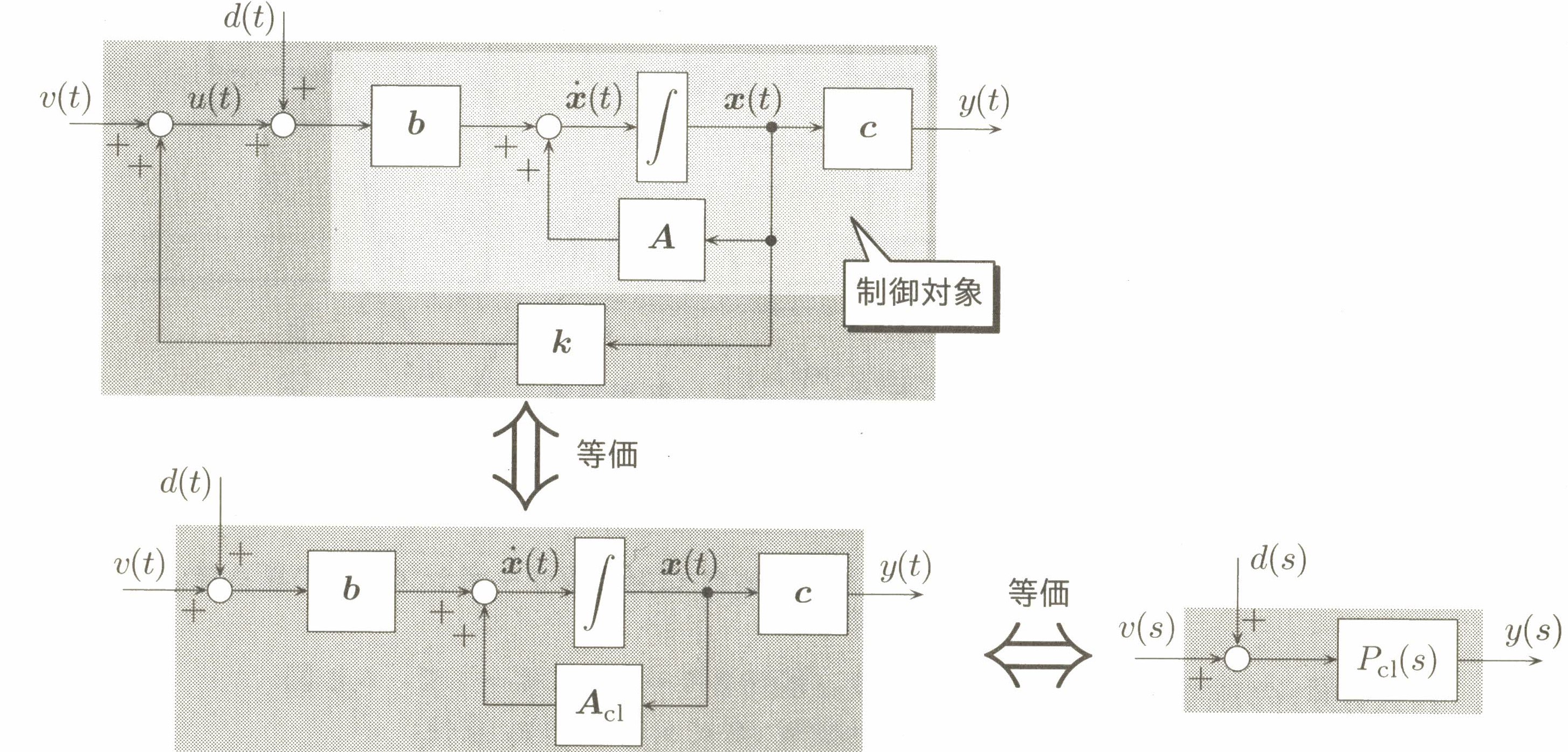
Figure 5.2

control target:

P:x˙(t)=Ax(t)+b(u(t)+d(t))y(t)=cx(t)                                                            (5.20)

state feedback:

K:u(t)=kx(t)+v(t)                                                            (5.21)

Pc1:x˙(t)=Ac1x(t)+b(v(t)+d(t)), Ac1=A+bky(t)=cx(t)                                              (5.22)

Pc1:y(s)=Pc1(s)(v(s)+d(s)), Pc1(s)=c(sI-Ac1)-1b                                              (5.23)


Theorem. Internal Model Principle


Figure 5.3 feedback control system

e(s)=yref(s)-y(s)                                     =yref(s)-Pcl(s)(d(s)+v(s))        =yref(s)-Pcl(s)(d(s)+Ccl(s)e(s))e(s)=yref(s)-Pcl(s)d(s)1+Pcl(s)Ccl(s)                                                       (5.24)

Reference and disturbance are step signal:

yref(t)=α1f(t), d(t)=α2(t)f(t)yref(s)=α1s, d(s)=α2s                      (5.25)

Decompose Pcl(s) and Ccl(s) in Num and Den:

Pcl(s)=NP(s)DP(s), Ccl(s)=NC(s)DC(s)                                        (5.26)

e(s)=DC(s)DP(s)α1-DC(s)NP(s)α2s(DP(s)DC(s)+NP(s)NC(s)):=DC(s)DP(s)α1-DC(s)NP(s)α2sΔcl(s)                    (5.27)

s=p1, , pN are the solutions of Δcl(s)=0 , if all of the roots p1, , pN are zero, the feedback control system in Figure 5.3 is Internal stable .
If there are no cancellations of Num and Den in Equation (5.27), e(s)=[e(t)] is:

e(s)=hs+k1s-p1++kNs-pN                                                   (5.28)

e(t)=-1[e(s)]=h+k1ep1t++kNepNte=h0                                   (5.29)

There is stationary error in Equation (5.29). Accordingly, modify construction of controller transfer function Ccl(s) as:

Ccl(s)=1s×NC(s)DC(s)                                                    (5.30)

e(s)=D~C(s)(α1DP(s)-α2NP(s))sΔcl(s) =k~1s-p1++k~Ns-pN                 e(t)=-1[e(s)]=k~1ep1t++k~NepNte=0                      (5.31)

Internal model principle [ref] :
Condition : reference and disturbance are step signal
Target : With step target yref(t) , input disturbance d(t) , steady-state deviation is zero ( e=0 )
Necessary and sufficient condition :
1. Feedback control system in figure 5.3 is internal stable.
2. Transfer function Pcl(s) has no zeros at origin s=0 .
3. Transfer function Ccl(s) has at least one integrator 1/s .
Further [ref] [note] :
Condition : reference and disturbance are normal signals other than step ones.
Using generating polynomial instead of integrator (actually it's a differentiator) in the denominator of Ccl(s) , see [note] .


5.2.2 状態フィードバック形式の積分型コントローラの設計

Figure 5.5 Integrator controller based servo control method

Kcl:v(s)=Ccl(s)e(s), Ccl(s)=g1sKcl:v(t)=g0te(t)dt                        (5.32)

For system as (p2):
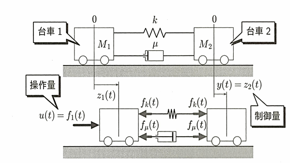
Figure 5.6 Two-cart inertial system
In a view of cart #1 state, a state feedback for cart #1 and I-PD controller for cart #2 is designed as:

K:u(t)=-kP1z1(t)-kD1z˙1(t)-kP2z2(t)+kI20te(t)dt-kD2z˙2(t)               (5.33)

which can be rewritten in 状態フィードバック形式( state variable feedback ) [ref] の積分型コントローラ as:

H:u(t)=-kP1-kD1-kP2-kD2z1(t)z˙1(t)z2(t)z˙2(t)+kI20te(t)dt                     (5.34)

State feedback style integrator controller:

K:u(t)=kx(t)+gω(t), ω(t):=0te(t)dt                          (5.35)

Consequently, does PD controller equal to feedback controller?
As [ref] said, "Proportional+Derivative (e.g. from PID) is a very similar to State Variable feedback for a second order system. The difference is in how you obtain the state variables." "PD says to use a derivative to obtain velocity in a 2nd order system."
In my opinion, PD controller is a output feedback, in many systems, say, position-velocity, voltage-current, etc. states can be obtained via derivation of output. Other system may use state observer.

Further reading:
Servo Motors and Industrial Control Theory.pdf chap3
Double Loop Control Design.pdf